


The Ambitious Light
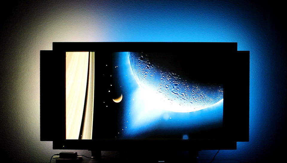 This project took me quite a while because of its unexpected complexity. It's a stand-alone ambient TV light based on the Arduino Due microcontroller board and works completely independent from other devices like a PC or the TV itself.
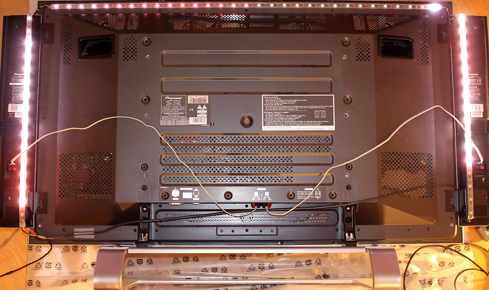
It takes an analogue video signal on the input and performs all necessary calculations to feed a RGB LED strip on the back of the TV.
This project took me quite a while because of its unexpected complexity. It's a stand-alone ambient TV light based on the Arduino Due microcontroller board and works completely independent from other devices like a PC or the TV itself.
It takes an analogue video signal on the input and performs all necessary calculations to feed a RGB LED strip on the back of the TV.
Now you might ask, why dealing with analogue video in times of HDMI and high definition video ?
Well, the answer is quite simple. I love my good old plasma TV from the mid 2000's and always wanted to extend it with a nice, vivid background light. And of course its great fun to see if its possible to decode video signals with the limited capabilities of an Arduino.
So let's get started and take a look at the main block diagram:
 As you can see the Arduino Due is surrounded by some other components which are more or less necessary to make it work. An RGB component video signal is fed into an input circuitry, which prepares the signal for Arduino's ADC inputs.
In fact this input circuitry serves three different purposes:
As you can see the Arduino Due is surrounded by some other components which are more or less necessary to make it work. An RGB component video signal is fed into an input circuitry, which prepares the signal for Arduino's ADC inputs.
In fact this input circuitry serves three different purposes:1. Sync extraction
As the color channels of a component video signal are lacking sync pulses the sync is extracted from a separate sync channel and then added to the three color channels.
2. Amplification
A standard PAL coded TV signal uses voltages in the range from approx. -0.3 to 1.0 volts. Since the ADC only accepts voltages between 0 and 3.3 Volts the signal needs to be amplified and shifted towards the positive voltage range.
3. Filtering
With some code tweaking the maximum sampling rate of Ardiuno Due's ADC can be increased to approximately 660 kHz. This is still not enough to handle the full 5 MHz bandwith of a PAL luma signal. So I added a simple adjustable low-pass filter for reducing unwanted frequencies.
For details on the circuit see chapter "Input Circuitry"
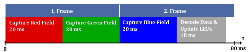
After pre-processing the color signals are fed into separate ADC inputs on the Arduino. Since we can capture only one channel at a time with the full speed of 660 kHz we need to apply a time interleaving technique in order to get all the information we need. This works as follows.
The LED chain consists of a number of WS2812B LED elements, which are all controllable via a single digital output pin of the Arduino. Every LED element reads and consumes its part of the data and sends the remaining parts to the next LED. Unfortunately the digital output pins of the Arduino Due deliver only 3.3 volts, which is a bit to weak for the WS2812B chips in order to work properly. That's why some kind of logic level converter has to be added to get a proper 5V data signal for the LEDs.
For the power supply I've choosen a 5V / 5A power adapter. It is capable of delivering enough current for at least 60-80 LEDs. Since 5V power adapters are quite uncommon I decided to add an overvoltage protection circuitry which blows a fuse in case someone is trying to connect a higher voltage rated supply by mistake.
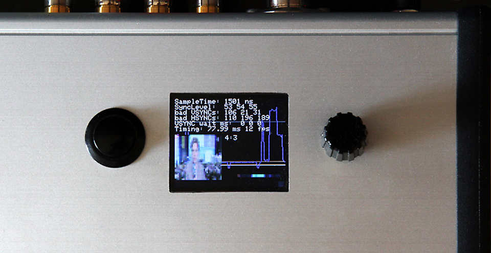
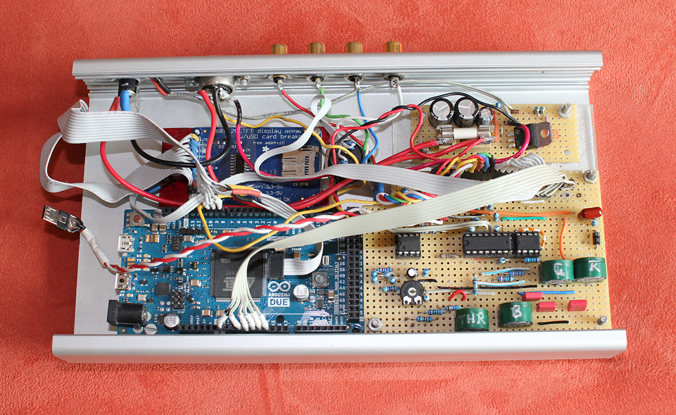
Due to the advanced complexity of the project, mainly the video decoding process, I decided to connect a little Adafruit TFT display for debugging purposes. It's got a resolution of 128x160 pixels and is connected via the SPI header on the board. The update rate is quite poor but it certainly does it's job. Since I also needed a way of displaying adjustment parameters like brightness, gamma, saturation etc. the little TFT eventually found it's way into the final metal case.
Input Circuitry
When dealing with analogue video signals there are some special things to keep in mind. First, every input channel has to be terminated with 75 Ohms in order to get the right voltages and to prevent the signal from ringing. Secondly, the received signal may be AC-coupled and thus have a varying DC offset. For proper decoding it is then crucial to re-establish a constant DC offset. This can be done by using a DC clamper consisting of a capacitor and a diode. The complete schematics for the pre-processing circuitry can be seen below. It includes two kinds of op-amps and one voltage comparator.
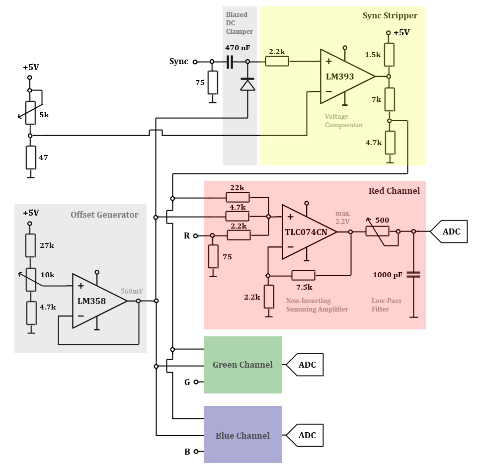
A LM358 op-amp is used to shift the RGB signals into the positive voltage range. For every color channel a high speed TLC047CN op-amp is used to amplify the signal. It also acts as a buffer for adding the offset and the sync pulse. The amplifier is followed by a simple first order passive low-pass filter in order to reduce unwanted frequencies and optimize signal distribution across the relatively small amount of samples taken by the Arduino.
Due to the fact that RGB component video is lacking sync pulses the sync has to be extracted from a dedicated sync channel, which is usually a standard composite video signal. A LM393 comparator is used to extract those sync pulses. The PAL TV standard defines sync pulses to be in the range of -0.3 to 0 Volts. So normally the comparator would have to deal with negative pulses and thus would need a negative voltage rail. To prevent this the DC clamper unit is already biased to a positive offset voltage.
Decoding and Image transformation
As previously mentioned the Arduino Due's ADC is capable of taking samples at a rate up to 660 kHz. The PAL TV standard defines the length of one horizontal line as 64 µs. Thus we are able to capture 42 samples per line. However, the length of the actual visible picture information is just 52 µs. So the amount of visible pixels is 34 per line.

Capturing three complete fields in a row at 660 kHz requires memory for buffering up to 40.000 samples. Since the Arduino Due provides only 96 kB of precious SRAM the 12 bit ADC data is truncated to 8 bits in order to save some memory. This by the way doesn't compromise the color reproduction, because the LED strip is also working with 8 bits for every color channel.
Once three fields of different colors have been captured the 34 x 34 RGB image is ready for further processing. White and black levels have to be taken into account and a low gamma curve has to be applied in order to match the brightness distribution of the TV display.
The complete source code can be downloaded here:
TVLight13.zip (16 kB)
The main features are:
- Decoding of a standard definition RGB component video signal (PAL)
- Color interpolation for left, right and top RGB LED chains
- Intelligent combination of border colors and central colors
- Color transformations (brightness, gamma, saturation, "Afterglow" etc.)
- Automatic detection of 16:9 or 4:3 content
- 12.5 fps refresh rate, < 80 ms latency
- TFT display support
- parameter storage on SD card due to the lack of an EEPROM
Construction
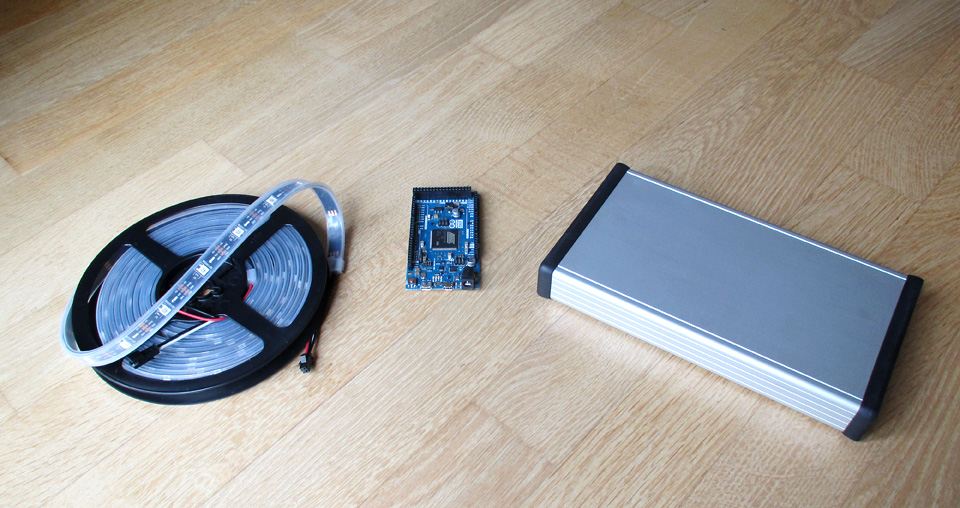
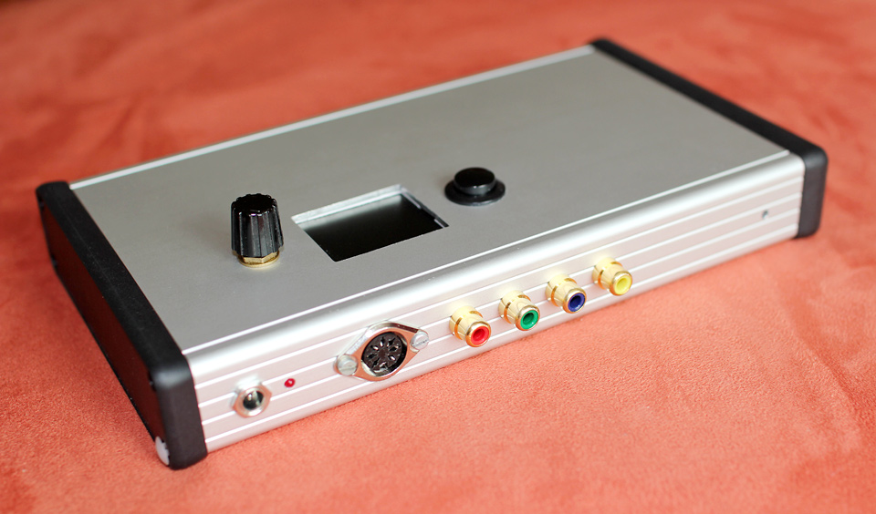
The actual built process went through three different construction phases: the electronics, the software and the mechanical work. Here are some pictures taken throughout the process:
So there you have it! A quite complex project, but I'm very pleased with the results.
If you have questions, comments or suggestions don't hesitate to contact me. Be creative & have fun!